
Use this reference for your project
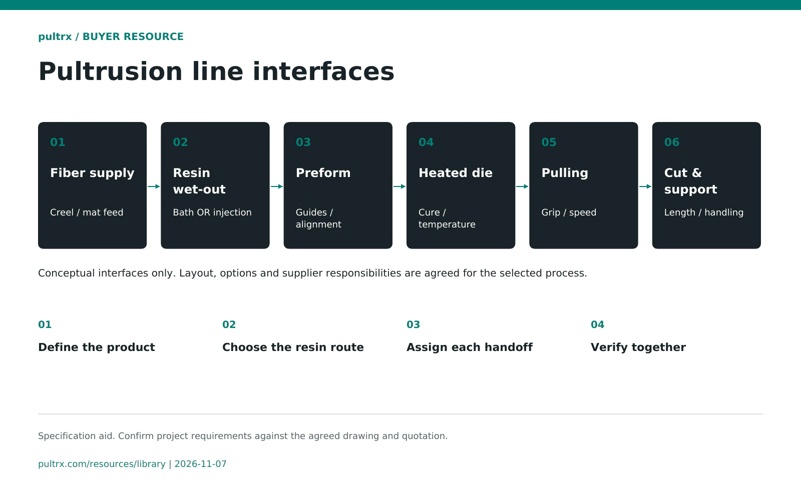
This pultrusion line interface map records the handoffs between six process functions. Use it to define what each supplier provides, what must connect and what evidence is needed at the agreed trial.
The process drawing is a configuration aid. Resin-bath wet-out and closed injection are process-dependent alternatives; do not read the map as a requirement to install both in series.
How to use it
- 01
Define the product
Start with the profile drawings, resin system, reinforcement and target output.
- 02
Choose the resin route
Confirm the wet-out or injection arrangement and its position relative to preforming.
- 03
Assign each handoff
Name the provider, receiver and approver for mechanical, utility and control interfaces.
- 04
Verify together
Agree a coordinated trial and record unresolved interfaces before shipment or installation.
Worksheet reference
Use these fields and checks with your project documents. Record the agreed values and evidence in the editable file.
| Process function | Interface to define | Scope owner to name | Evidence to agree |
|---|---|---|---|
| 1. Reinforcement supply | Packages, fiber path, guides and tension arrangement | Creel / reinforcement tooling supplier | Material setup and fiber-path review |
| 2. Resin impregnation | Bath wet-out OR injection, selected for the process | Bath tooling or injection-equipment supplier | Material compatibility and agreed delivery checks |
| 3. Preforming | Guide sequence, reinforcement placement and die entry | Die and preform-guide supplier | Approved arrangement and trial inspection |
| 4. Heated die | Mounting, envelope, heaters, sensors and receiving line | Die supplier and heating / controls provider | Interface drawing and trial sample records |
| 5. Pulling | Grip or track contact, alignment and start/stop sequence | Pulling-machine supplier | Agreed profile trial and control handoff |
| 6. Cut-off and handling | Length control, cutting, extraction and receiving supports | Cut-off / handling supplier and site team | Cut-length checks and agreed handling scope |
Scope and reading notes
- These are process functions, not a scale layout. Station order and integration depend on the profile, resin route and supplier design.
- Name Haoli for its machinery, Henan Zhongsheng for its dies and tooling, and Huafan where its PU injection system is selected. Confirm each legal party and responsibility in the quotation.
- Agree utilities, interlocks, installation and acceptance as a coordinated scope. Equipment FAT does not establish finished-product conformity.
Sources and supporting references
Prepared by pultrx from the references below. Follow the linked product or guide for the full scope and source conditions.